LIST OF EXAMPLES
|
|
3D-VIEW & LINK
|
SPECIFICATION
|
DESCRIPTION
|
|
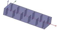
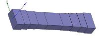
WR-62 Receive-Reject Filter
Pass-Band: 17.3 - 18.4 GHz
Insertion Loss: 0.07 dB
Return Loss: 25 dB
Rejection: 90 dB @ 12.75 GHz
|
Waveguide H-plane Iris Filter
This filter is realized as a sequence of thin full-height diaphragms (windows) in a rectangular waveguide. It is the most old, simple, popular, reliable and manufacturable waveguide band-pass filter solution. The design procedure is simple and well known among filter designers [1,2,3].
|
|
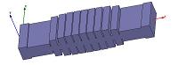
WR-75 Transmit-Reject Filter
Pass-Band: 10.7 - 12.75 GHz
Insertion Loss: 0.09 dB
Return Loss: 25 dB
Rejection: 50 dB @ 13.75 - 14.50 GHz
|
Waveguide E-plane Iris Filter
The filter is realized as a sequence of thin full-width diaphragms (windows) in a rectangular waveguide. This type of structure can be used as a low-pass filter to cut off unwanted spectrum higher than the pass-band. By implementation it is similar to E-plane stub [4] or corrugated filters [5,6,7]. WR_Connect provides templates for the both types as design starting point.
|
|
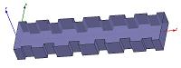
WR-137 Receive-Reject Filter
Pass-Band: 5.85 - 6.45 GHz
Insertion Loss: 0.04 dB
Return Loss: 25 dB
Rejection: 80 dB @ 3.7 - 4.2 GHz
|
Waveguide Filter with Thick Irises
This filter is a type of H-plane iris filter using thick irises. It is known that iris filters usually demonstrate more rejection at lower roll-off and less rejection of higher frequencies. Increasing thickness of diaphragms would gain the effect and make the frequency response closer to high-pass type.
|
|
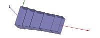
WR-75 to WR-62 Transition
Pass-Band: 11.0 - 15.0 GHz
Insertion Loss: 0.01 dB
Return Loss: 30 dB
|
Stepped-Impedance Transformer
WR-Connect provides a template for projecting an exponentially matched transformer for different waveguide interfaces.
|
|
WR-75 High-Pass Filter
Pass-Band: 10.0 - 15.0 GHz
Insertion Loss: 0.05 dB
Return Loss: 30 dB
Rejection: 60 dB @ 8.0 GHz
|
H-plane Stepped Waveguide Filter
Using a cut-off section of waveguide as natural high-pass filter is quite old and still preferable for designers. This filter is based narrow waveguide section matched with interface by two transformers. Using WR-Connect you can design such a filter as simple as a transformer.
|
|
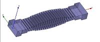
WR-112 Corrugated Harmonic Filter
Pass-Band: 7.9 - 8.4 GHz
Insertion Loss: 0.10 dB
Return Loss: 25 dB
Rejection:
65 dB @ 10.5 GHz (roll-off)
80 dB @ 15.8 - 16.8 GHz (2nd harmonic)
80 dB @ 23.7 - 25.2 GHz (3rd harmonic)
60 dB @ 31.6 - 33.6 GHz (4th harmonic)
|
Tapered Corrugated Low-Pass Filter
Periodically corrugated waveguide filters were originated by Conh [5]
and much upgraded to aperiodic tapered structures by Levy [6,7].
Despite the presence of spurious responses corresponding to high order modes,
this type of low pass filter is very popular due to its simplicity,
low insertion loss and high power handling. Design tools are here:
Corrugated Low-pass Filter Design Workshop
WR-Connect: Corrugated Waveguide Low-Pass Filter
|
|
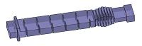
WR-112 Band-Pass Filter
Pass-Band: 8.20 - 8.45 GHz
Insertion Loss: 0.15 dB
Return Loss: 25 dB
Rejection:
60 dB @ DC - 7.65 GHz
60 dB @ 9.0 - 18.0 GHz
|
Composite H-plane / Corrugated Filter
The idea of cascading a band-pass iris filter with a corrugated low-pass filter is not new indeed, however using WR-Connect you could design the cascade as a single unit, make it smaller, less loss and free of spurious spikes caused by propagation of high-order modes.
|
|
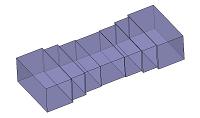
WR-75 Spurious Suppression Filter
Pass-Band: 11 - 15.0 GHz
Insertion Loss: 0.02 dB
Return Loss: 30 dB
Rejection @ 15-17 GHz:
30 dB TE20-mode
30 dB TE01-mode
|
TE20 & TE01 Modes Rejection Filter
This waveguide structure is used to reject spurious spectrum carried by TE20 and TE01 modes. It can be used in combination with a conventional cavity filter and gain far-out-of-band rejection with almost no insertion loss increase. Using WR-Connect you can design a filter like this for 50 seconds in three steps (transformer template, transformer synthesis, connection to its Z-flip).
|