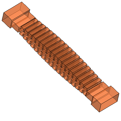
This tool is designed to synthesize a preliminary (a "good starting point")
design concept of a low-pass filter based on an E-plane corrugated and generally inhomogeneous
[1] waveguide.
Corrugated low-pass filters are in great demand in modern microwave technology and
many engineering papers, reports and patents have been recently published
(see selected references [1-13]).
For a beginner designer, for a start, it is advised to look through some of these
works to find out about the theoretical and practical foundations.
All corrugated waveguide filters researched in referenced papers are divided here
in three categories (listed in next paragraphs). This design tool can be applied
(directly or indirectly) to all three types of waveguide structures, but the
design method used here, however, may differ from
the original sources.
Regular Corrugated Filters
These are the filters with a constant width of the waveguide channel [2,3,6,8-12].
Such filters suffer from the presence of spurious pass-bands (responses) [1]
corresponding to propagation of higher order waveguide modes of
TEN0
origin (where N>1).
Nevertheless, the regular corrugated filters can be very efficiently used
as harmonic (up to 17 harmonics claimed in [10])
reject filters. In other words, these filters can be preferably used to reject
a sparse frequency-scattered spurious interference (for example,
harmonics of a transmitter or amplifier). The obvious their advantages
are the simplicity, reliability and accuracy. Before you start designing
with this tool,
try the "Corrugated Low-pass Filter Design Workshop",
which was designed to create a simple "cost-effective" harmonic-reject filter
of this type.
Plus, all design steps (spurious layouts, initial synthesis, simulation,
optimization, and sensitivity analysis) perform much faster there.
On the contrary, it is advised to use this tool only for more complex designs,
which require more flexibility in profiling the corrugations.
Iregular Corrugated Filters
These are the filters with the width of the waveguide channel not being constant,
but smoothly changing (tapered way) along its length. Such filters are called
here as "irregular" ("inhomogeneous" in [1]). The reason for tapering the channel width
is that it significantly narrows the spurious responses.
Here, the designer is advised to smoothly expand the channel width from a minimal
dimension (A min) at one end to a maximal dimension
(A max) at the other end. The dimension (A min)
should be slightly greater than the half the wavelength corresponding to the lower
frequency bound of the targetted pass-band and the dimension (A max) should be
slightly less than the full wavelength corresponding to the upper bound
of the targetted pass-band. This channel width range ensures that the pass-band
is above the dominant mode (TE10) cut-off and below the first spurious mode
(TE 20) cut-off.
Composite Corrugated Filters
These filters are composed from sections (sub-filters),
which are based on regular corrugated channels [4,5,7].
Those sub-filters cover the same pass-band for the dominant mode TE10-mode
and have different layouts of pass-bands corresponding to spurious TEN0-modes (N>1).
Such filters, as claimed in [4,5]), can be designed to completely stop all spurious transmission
and perform better than waffle-iron filters. But in this case, the designer actually needs to design
two filters (not necessarily finalized) and connect them to each other (after removing the
extra sections of transformers).
Design Method
The proposed method for designing a waveguide corrugated filter is based on matching
a "slightly" aperiodic corrugated structure of the waveguide channel with the input
and output interfaces at a single frequency point (center frequency) [4].
In this case, the corrugated waveguide is represented as an ideal transmission line,
but with impedance smoothly varying along the length. Then, such a line is matched
to the input and output interface with appropriate quarter-wave transformers at the
specified center frequency. Thus, matching with good return loss typically only occurs in
a narrow bandwidth and degrades away from the center frequency. Nevertheless, such
synthesis method usually leads to a good starting filter concept and can be further
easily optimized to meet users preferences. However, prior to optimization, the user
is advised to perform a full modal analysis to ensure that the preliminary design
concept does not suffer from spurious responses and meets the specified rejection
goals with adequate margins.
Getting Started
This tool can be directly used (in a straight forward way) to design the first two types
of corrugated waveguide filter (regular and iregular). It is also can be used to design a
composite corrugated waveguide filter, consisting from parts such as filters of two first types.
In that case, however, the user is expected to do some additional work on composing the filter
from the parts (using structure editor) and matching them with each other and I/O interface
(more optimization would be required). Anyway, in all cases, the starting procedure is as follows:
Select the I/O waveguide (EIA standard) interface in the top row of table
and click "Set Initials" button. This will derive some initials for the
internal corrugated waveguide channel and its profile. Those initial
settings are based on a common sense guess and can be changed later.
The user can also set those parameters manually.
Correct or set the centrer frequency in the second row.
Correct or set the proper ("non-spurious") width of corrugations in case
of a regular corrugated filter or their range of tapering in case of
iregular corrugated filter. Those A-dimensions (first numbers in the input fields
located in 4th and 5th table rows) effect the layout of
the spurious.
In a similar manner, set the vertical profile of the corrugated channel, i.e.
the B-dimensions for the irises and cavities forming aperiodic and tapered
corrugated waveguide on E-plane. It is suggested, that the larger corrugations
work for the lower frequencies and, vice versa, the smaller corrugations
are more efficient at higher frequencies. In a rough interpretation,
we need spread their efficiency bands across the entire cutoff range
with no gaps left.
The third number (iris thickness or cavity length) in each text field (in
4th and 5th table rows) can be left same or also be
variable. It is generally recommended to keep the iris thickness as thin as
technologically acceptable. The cavity length, however, should be reasonably
great to achieve a good loaded Q.
Set the number of corrugations or keep the default value.
Set the "Profile Factor" or keep the default value. This factor defines
how the appropriate dimensions of corrugations are distributed over the
waveguide channel. For example, a harmonic filter designed to reject
2nd and 3rd
harmonics should have more smaller corrugations than the one intended to
reject just the 2nd harmonics (appropriate guessed
values of this parameter can be 1-1.5 and 1.5-2.5).
Click "Setup Project" button (in case if the project has not been set yet).
This action will automatically set initial project settings with a frequency
sweep as the interface waveguide operational frequency range
(as EIA standard). It is required at least once to set the frequency plans,
but it can be changed or modified on the "Setup Page". If the project is already
set, clicking "Setup Project" could not be required as it would overwrite the
settings.
Click "Design Filter" button. The action will generate the filter connectivity
schematic, initial dimensions and navigate to the Editor Page with design
and simulation tools.
Finalize the design in the "Editor Page":
1) Verify if the initially
generated structure has a right frequency layout. I.e. the targetted pass-band
is located where the return loss is most higher and the roll-off is giving
adequate rejection in upper near-band (if required).
2) Run some other waveguide modes also. Make sure that spurious pass-bands
are out of targetted stop-band specs.
3) Make necessary adjustments to fit the pass-band, stop-band and spurious
if needed. To do so, try different corrugations dimensions at the ends and
the middle (4th and 5th rows of table).
4) Optimize (when finalizing) the in-band performance using optimization tool. Optimization
targets must be set (Setup page) prior to optimization.
Related Information Sources
[1] R. Levy, "Inhomogeneous stepped-impedance corrugated waveguide
low-pass filters," in IEEE MTT-S Int. Microw. Symp. Dig., Jun. 2005,
pp. 123–126.
[2] S.B. Conh "A theoretical and experimental study of a waveguide filter structure",
Office Naval Res., Cruft Lab., Harvard Univ., Cambridge, Mass., Rep. 39,
Apr. 25, 1948.
[3] R. Levy, “Tapered corrugated waveguide low-pass filter,” IEEE Trans .
Microwave Theory Tech., vol. MTT-21, pp. 526–532, August 1973.
[4] R. Goulouev, "New Type of Spruriosless Waveguide Harmonic Filter,"
manuscript, 2004.
Available here
[5] F. De Paolis, R. Goulouev, J. Zheng, and M. Yu, "CAD procedure
for high-performance composite corrugated filters," IEEE Trans.
Microw. Theory. Techn., vol. 61, no. 9, pp. 3216–3224,
Sept. 2013.
[6] W. Hauth, R. Keller, and U. Rosenberg, “CAD of waveguide low-pass
filters for satellite applications,” in Proc. 17th Eur. Microw. Conf.,
Rome, Italy, 1987, pp. 151–156.
[7] W. Hauth, R. Keller, U. Rosenberg, "The Corrugated-Waveguide Band-Pass Filter
- A New Type of Waveguide Filter", 18th EUMC Proc., Stockholm, 1988, pp.
945-949.
[8] O. Ishida, H. Maruf, "Expansion of a Continuous Stop Band of
a Corrugated Waveguide by Attenuation Pole Control," Proceedings
of APMC 2012, Kaohsiung, Taiwan, Dec. 4-7, 2012.
[9] R. Goulouev, “Corrugated Waveguide Filter Having Coupled Resonator Cavities”,
US Patent 6,169,466, Jan. 2001.
Available here
[10] R. Goulouev, D. Garcia, Q. Shi, C. McLaren, "Powerful Multiple Harmonics
Reject Filter Design, Testing and Acceptance Considering Ultra Overmoded
Waveguide Conditions," 5th Workshop on Advanced RF Sensors and Remote
Sensing Instruments, ESA/ESTEC, ARSI’17, vol. 1, Noordwijk, Netherlands, 2017.
Available here
[11] O. Monerris, P. Soto, S. Cogollos, V. E. Boria, J. Gil, C. Vicente, and B.
Gimeno, "Accurate circuit synthesis of low-pass corrugated waveguide filters,"
in Microwave Conference (EuMC), 2010 European, 2010, pp. 1237-1240.
[12] I. Arregui, I. Arnedo, A. Lujambio, M. Chudzik, D. Benito, R.
Jost, F. -1. Gortz, T. Lopetegi, and M. A. G. Laso, "A compact
design of high-power spurious-free low-pass waveguide fiters,"
IEEE Microw. Wireless Compon.Lett., vol. 20, no. 11, pp. 595-
597, Nov. 2010.
[13] F. Teberio, I. Arregui, A. Gomez-Torrent, I. Arnedo,
M. Chudzik, M. Zedler, F.-J. Gortz, R. Jost,
T. Lopetegi, and M. A. G. Laso,
"Chirping Techniques to Maximize the Power-Handling Capability
of Harmonic Waveguide Low-Pass Filters," IEEE MTT, v. 64, No. 9, Sept. 2016, pp.
2814-2823.