Composite Filter CAD Procedure based on Variational Approximations
Rousslan
A. Goulouev, E-mail: gouloue@ieee.org
Abstract
Multi-modal variational
approximations for scattering parameters of general triple-discontinuity
non-ideal cavity are expressed in terms of aperture integrals. Solution is
derived for different types of cavity junctions as convergent two-dimensional
sums of elementary functions. The filter or diplexer is considered as number of
such cavities connected by uniaxial waveguide
sections with dominant mode taken into account and linked with interface by
uniform waveguides, probes, loops or apertures. Design approach is based on
direct optimization of composite structures compiled from pre-synthesized
filters. The approach is used to create a fast running CAD tool successfully
used for design of variety of filters for SATCOM and wireless applications.
Introduction
Modern technical requirements
to filters and multiplexers are usually based on hard-hitting goals for pass-band
performance, roll-off, harmonics rejection, high power handling and
manufacturability, which often cannot be matched by conventional filters.
Therefore, filter design engineers are often looking for composite design
solutions using different type of scattering elements or parts of different
filters integrated into a complex filter structures. However, the popular full
wave software based on rigorous and universal numerical methods is practically
not suitable for design synthesis, optimization, proposals and sensitivity
analysis, requiring frequentative computations, because of slowness and
awkwardness. Therefore, popular engineering design procedures are based on common
equivalent circuits for discontinuities [1] connected by long transmission
lines loaded with irises or stubs convenient for fast analysis, design
proposing and design of conventional tunable hardware. However, lack of accurate
equivalent circuits for waveguide discontinuities quite limit variety of applications
and accuracy of cascading the discontinuities by ideal transmission lines is
not adequate for cavity filters. In paper [2] a multimodal variational
formulation is used for characterization of propagation in cavities of ridged
evanescent-mode filters and approximations are derived for 2x2 Y-matrix expressed
in terms of sums of integrals corresponding to junction apertures. Here double
discontinuity model formulated in [2] is corrected by taking propagation loss into
account and extended to triple discontinuity by inserting single or double
E-/H-plane posts or probes. Closed form solutions are derived for Y-matrix in
terms of aperture integrals corresponding to internal junctions and interface
connections. Thus filter or diplexer is represented by a number of pre-calculated
aperture integrals and distances between discontinuities. As the obtained
expressions are based on summation of elementary functions, they can be
compiled into fast running computer code, an effective design tool.
Cavity Model
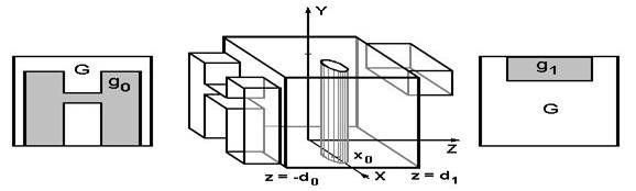
Figure
1: A triple discontinuity as a cavity with post or probe.
Here double discontinuity
model used in [2] is generalized for case of propagation loss and extended to
triple discontinuity by inserting single or double E-/H-plane posts or probes
(see Figure 1). The current distribution on posts and probes is represented in
terms of monopole and dipole current lines,
![]() .
.
Thus additional terms Anm
representing scattering on posts,
![]() ,
,
are added into basic
formulation for cavity E-field used in [2] . Analogically matching continuity
of magnetic and electric fields on apertures and boundary conditions on planes
of junctions,![]() , posts or probe
, posts or probe
![]() ,
,
can obtain expressions for
elements of Y-matrix,![]() , in terms of vectors of field integrals associated with the
both apertures, where Y0 is 2x2 Y-matrix of cavity [2] without post
or probe with surface loss corrections and ΔY is an addition inserted by
post (2x2 matrix) or probe (3x3 matrix). Additional mathematical manipulations
are applied for probe models to extract irregularity associated with voltage
gap [3].
, in terms of vectors of field integrals associated with the
both apertures, where Y0 is 2x2 Y-matrix of cavity [2] without post
or probe with surface loss corrections and ΔY is an addition inserted by
post (2x2 matrix) or probe (3x3 matrix). Additional mathematical manipulations
are applied for probe models to extract irregularity associated with voltage
gap [3].
Results and Comparison
The obtained expressions have
been compiled into computer algorithms synthesizing initial dimensions,
simulating and optimizing frequency response. Design procedure for composite
filters and diplexers based on synthesis of primary filters, putting them
together and optimizing over spec constrains has been developed. Although the
computational approach takes only dominant mode into account between cavities,
the simulation results for long filter structures with narrow gaps [4] can be
even more accurate than obtained by rigorous FEM based simulators (see Figure
2). The design procedure has been applied to variety of waveguide filters, such
as tapered corrugated [5], quarter-wave-coupled corrugated [4], composite asymmetric
corrugated [6] (see Figure 4), H-plane iris, resonant iris and evanescent-mode
ridged. It has also applied to closed surface ceramic filters (see Figure 3)
and diplexers (see Figure 5) representing circular resonators as equivalent short
sections of ridged or asymmetric double ridged waveguides. Accuracy of simulation
is found practically acceptable in respect to production tolerances and tuning
margins for majority of designs. However, the simulation time over discreet
sweep of two hundred frequency points performed not longer than a second, which
is about 30000 times faster than time required by HFSS, a universal FEM based
simulator, installed on the same UNIX platform.
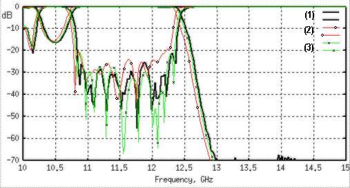
Figure
2: Comparison between data measured (1), computed using FEM (HFSS)(2) and presented approach (3) for a Ku-band corrugated
harmonic filter.
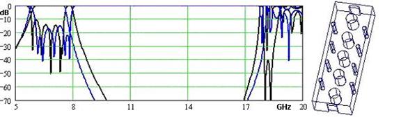
Figure
3: Response of ceramic filter obtained by presented method and FEM
(HFSS).
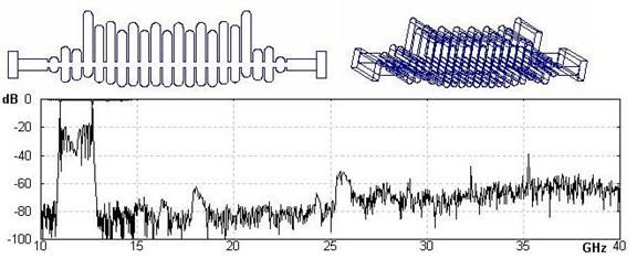
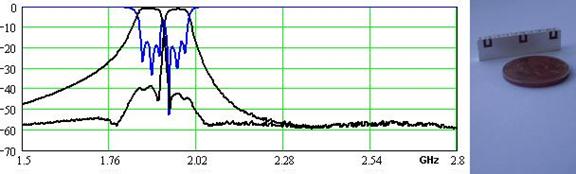
Figure
4: Appearance and measured response of a composite corrugated filter
designed using this method.
Figure
5: Measured frequency response of a closed surface ceramic PCS diplexer
designed using presented method.
References
[1] N. Marcuvitz, Waveguide Handbook,
[2] J.C. Nanan, Jun-Wu Tao, H. Baudrand, et
al, A Two-Step Synthesis of Broadband Ridged Waveguide Bandpass
Filters with Improved Performances, IEEE, MTT-39, Dec. 1991, pp. 2192-2197.
[3] L. Lewin, Theory of Waveguides, Newnes-Buterworth,
1975.
[4] R. Goulouev
Corrugated Waveguide Filter having Coupled Resonator Cavities, US Patent 6,169,446
[5] R. Levy, Tapered
Corrugated Waveguide Low-Pass Filters, IEEE, MTT-21, Aug. 1973, pp. 526-532.
[6] R. Goulouev
Waveguide Filter Having Asymmetrically Corrugated resonators, US Patent
6,232,853.